The Apparent Resistivity Calculator is an indispensable tool used in geophysics, particularly in the field of electrical resistivity surveys. This calculator helps scientists and engineers determine the electrical resistivity of the ground at various depths, which is crucial for identifying underground features such as water tables, mineral deposits, and fault lines. By measuring how strongly the ground resists or conducts electrical current, this tool plays a pivotal role in environmental assessments, mining explorations, and infrastructure development.
Formula for Calculating Apparent Resistivity
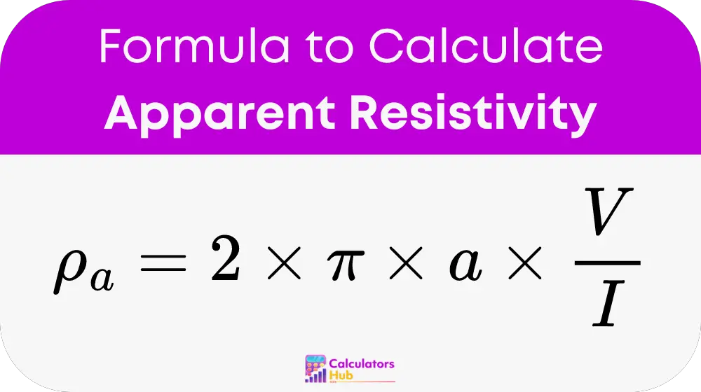
To achieve accurate measurements, the Apparent Resistivity Calculator employs a formula based on the Wenner Array method, one of the most common electrode configurations in resistivity testing:

Detailed Breakdown:
- ρ_a: Apparent resistivity, typically measured in ohm-meters (Ωm).
- π (pi): A mathematical constant, approximately equal to 3.14159.
- a: Spacing between the electrodes, which can be adjusted based on the depth of survey.
- V: Potential difference measured between the potential electrodes.
- I: Current introduced into the ground through the current electrodes.
This formula is vital for converting raw measurements of voltage and current into a meaningful resistivity value, which reflects the subsurface properties.
Practical Application: Reference Table
For practical application and to assist users, here is a reference table showing typical resistivity values for various subsurface materials:
| Material | Typical Resistivity (Ωm) |
|---|---|
| Fresh Water | 100 to 500 |
| Clay | 10 to 100 |
| Sandstone | 10 to 1,000 |
| Granite | 1,000 to 10,000 |
| Limestone | 100 to 1,000 |
These values demonstrate the variability of electrical resistivity depending on the material composition and conditions.
Example of Apparent Resistivity Calculation
Let's consider a practical scenario where a geophysical team measures a potential difference of 0.5 volts and introduces a current of 2 amperes through electrodes spaced 50 meters apart:
- a: 50 meters
- V: 0.5 volts
- I: 2 amperes
Using the formula:
- Apparent Resistivity (ρ_a) = 2 * 3.14159 * 50 * 0.5 / 2 = 157.08 Ωm
This calculation helps geophysicists evaluate the subsurface characteristics, aiding in precise decision-making for exploration or construction projects.
Most Common FAQs
Soil moisture significantly lowers resistivity, as wetter soils conduct electricity better than dry soils.
Apparent resistivity helps identify the distribution of groundwater and contaminants, which is crucial for environmental protection and remediation efforts.
Yes, temperature can affect resistivity; colder conditions generally increase resistivity due to reduced ion mobility in the soil.