A Crosstalk Coefficient Calculator helps engineers and designers measure the level of unwanted signal interference between adjacent transmission lines in electrical circuits, communication systems, and printed circuit boards (PCBs). Crosstalk occurs when signals in one channel interfere with signals in another, reducing signal integrity and causing data errors.
The crosstalk coefficient (CT) quantifies the impact of interference by comparing the power of the desired signal to the power of the interfering signal. By calculating the crosstalk coefficient, engineers can assess the level of noise in a system and take necessary corrective measures such as shielding, adjusting spacing, or using differential signaling.
This tool is widely used in RF engineering, telecommunications, audio systems, and high-speed PCB design to ensure clear signal transmission and minimize interference.
Formula of Crosstalk Coefficient Calculator
The crosstalk coefficient (CT) is calculated using the following logarithmic formula:
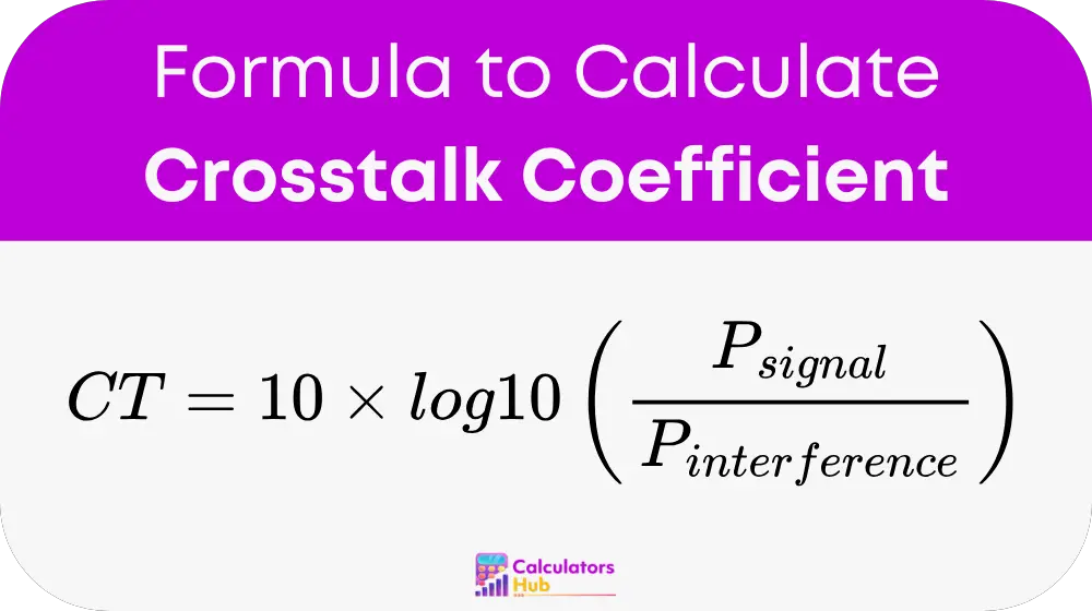
Where:
- P_signal = Power of the desired signal (in watts or milliwatts)
- P_interference = Power of the interfering signal (in watts or milliwatts)
- 10 × log10 is used to convert the ratio into decibels (dB), which is a standard measurement in signal processing.
A higher crosstalk coefficient (in dB) indicates less interference, while a lower value means stronger interference and possible signal degradation.
Pre-Calculated Crosstalk Coefficient Table
The following table provides estimated crosstalk coefficients (CT) in decibels (dB) for common signal and interference power ratios:
| Signal Power (P_signal) | Interference Power (P_interference) | Crosstalk Coefficient (CT) (dB) |
|---|---|---|
| 10 mW | 1 mW | 10 dB |
| 10 mW | 0.1 mW | 20 dB |
| 100 mW | 1 mW | 20 dB |
| 100 mW | 10 mW | 10 dB |
| 1 W | 0.01 W | 20 dB |
This table provides a quick reference for estimating interference levels without manual calculations.
Example of Crosstalk Coefficient Calculator
Let’s calculate the crosstalk coefficient for a system where:
- Desired signal power (P_signal) = 100 mW
- Interference power (P_interference) = 1 mW
Using the formula:
CT = 10 × log10(100 / 1)
CT = 10 × 2 = 20 dB
This means the crosstalk coefficient is 20 dB, indicating that the signal is significantly stronger than the interference, ensuring good signal integrity.
Most Common FAQs
The crosstalk coefficient helps engineers quantify interference levels in electronic circuits, ensuring reliable signal transmission in communication systems, PCBs, and RF circuits.
To reduce crosstalk, you can:
Increase spacing between signal traces.
Use shielding or ground planes.
Implement differential signaling to minimize noise.
A crosstalk coefficient of 20 dB or higher is generally considered acceptable for most applications. Values below 10 dB indicate significant interference, requiring design adjustments.