The Antenna Trap Calculator is an indispensable tool for amateur radio enthusiasts and professional communication engineers who design and utilize multi-band antennas. It aids in calculating the resonant frequency of an antenna trap, which is crucial for allowing a single antenna to operate effectively at multiple frequency bands. By using traps, antenna builders can create compact, efficient antennas capable of operating on various bands without the need for multiple separate antennas.
Formula of Antenna Trap Calculator
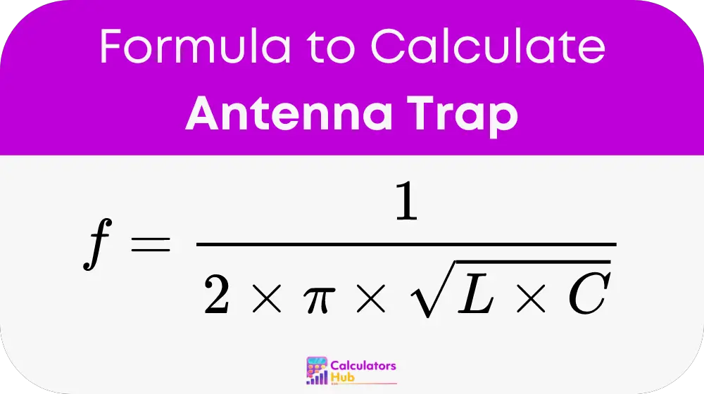
The calculation of the resonant frequency for an antenna trap is based on its inductance (L) and capacitance (C). The formula used is:
Detailed Explanation
- f: Resonant frequency in hertz (Hz).
- L: Inductance in henries (H).
- C: Capacitance in farads (F).
- π: Mathematical constant, approximately equal to 3.14159.
Steps for Calculation
- Determine the desired inductance (L): This is usually dictated by the physical properties and design of the trap.
- Specify the capacitance (C): Chosen based on the required frequency and bandwidth.
- Calculate the resonant frequency (f): Plug the values of L and C into the formula to determine the frequency at which the trap will resonate.
General Reference Table
To facilitate easier understanding and application, here's a table that provides typical values for L and C and the resulting resonant frequencies:
| Inductance (L) | Capacitance (C) | Resonant Frequency (f) |
|---|---|---|
| 1 mH | 100 pF | 5.03 MHz |
| 2 mH | 200 pF | 2.52 MHz |
| 0.5 mH | 50 pF | 10.06 MHz |
This table demonstrates how varying L and C affect the resonant frequency, aiding users in designing traps for specific frequency bands.
Example of Antenna Trap Calculator
Imagine designing an antenna trap for a frequency of 7.1 MHz. Assuming you choose an inductance of 1.2 mH and need to find the required capacitance:
Using the resonant frequency formula:
- Rearrange to solve for C: C = 1 / (f^2 * 4 * π^2 * L)
- Plug in the values: C = 1 / ((7.1 * 10^6)^2 * 4 * 3.14159^2 * 1.2 * 10^-3)
- Calculate C ≈ 47.88 pF
Thus, for a trap designed to operate at 7.1 MHz with an inductance of 1.2 mH, a capacitance of approximately 47.88 pF is required.
Most Common FAQs
An antenna trap is a parallel combination of an inductor and a capacitor inserted in an antenna element. It allows the antenna to operate at multiple resonant frequencies, effectively making it a multi-band antenna.
Antenna traps allow for the construction of shorter, more compact multi-band antennas without sacrificing performance, ideal for space-restricted installations and for reducing visual impact.
Selecting the right L and C values depends on the specific bands you wish to operate on and the physical constraints of your antenna design. It typically involves balancing performance, bandwidth, and physical size.