This calculator measures the resistance an I Beam offers when subjected to bending. It calculates the moment of inertia along the horizontal (X-axis) and vertical (Y-axis) axes, crucial for evaluating the beam’s capacity to bear different types of loads.
Formula of I Beam Moment of Inertia Calculator
For the moment of inertia around the X-axis (horizontal axis), the formula is:

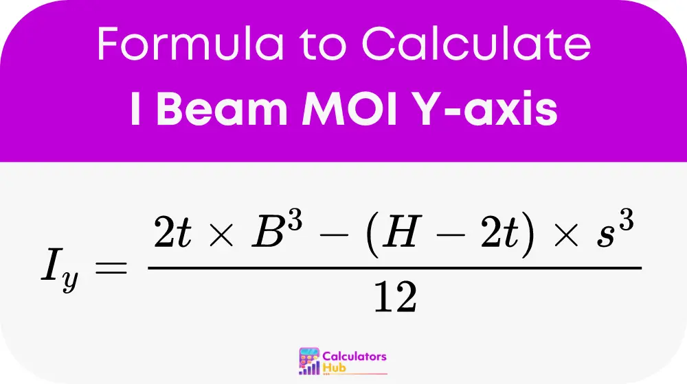
For the moment of inertia around the Y-axis (vertical axis), the formula is:

Where:
- B is the width of the flange (top and bottom).
- H is the total height of the I-beam.
- t is the thickness of the flange.
- s is the thickness of the web.
These calculations help design and engineer I Beams accurately to support intended loads without failure.
Application Table
Here is a table with common values for B, H, t, and s, and their resulting moments of inertia:
| B (cm) | H (cm) | t (cm) | s (cm) | Ix (cm4) | Iy (cm4) |
|---|---|---|---|---|---|
| 15 | 30 | 1.5 | 0.6 | 67500 | 900 |
| 20 | 40 | 2 | 0.8 | 213333 | 2133 |
| 25 | 50 | 2.5 | 1 | 520833 | 4167 |
Example of I Beam Moment of Inertia Calculator
If an I Beam has a flange width (B) of 20 cm, height (H) of 40 cm, flange thickness (t) of 2 cm, and web thickness (s) of 0.8 cm, using the formulas:
Calculated Ix: Ix = [20 * 40^3 – (20 – 0.8) * (40 – 4)^3] / 12 = 213333 cm4
Calculated Iy: Iy = [4 * 20^3 + (40 – 4) * 0.8^3] / 12 = 2133 cm4
These results determine the beam’s performance in construction.
Most Common FAQs
The moment of inertia indicates the beam’s resistance to bending, ensuring that structures can handle expected loads safely.
Change the input values (B, H, t, s) based on the I Beam’s dimensions to get accurate results for any size.
Information on digital tools and apps for similar calculations is available for onsite and remote use.