The Buckling Effect Calculator is a vital tool for engineers and designers working in structural mechanics, civil engineering, and mechanical engineering. It helps determine the critical load at which a slender column or structural element will buckle when subjected to axial compression. Buckling is a failure mode that occurs when a structural member experiences a sudden sideways deflection under an axial load, leading to collapse. This calculator provides accurate estimates of the maximum axial load a column can withstand before it loses stability and buckles.
Knowing the buckling load is essential for ensuring structural safety, particularly in tall buildings, bridges, machinery supports, and other applications involving long, slender members. By using the Buckling Effect Calculator, engineers can assess whether a column or beam will fail under given loads, helping prevent potential catastrophic failures.
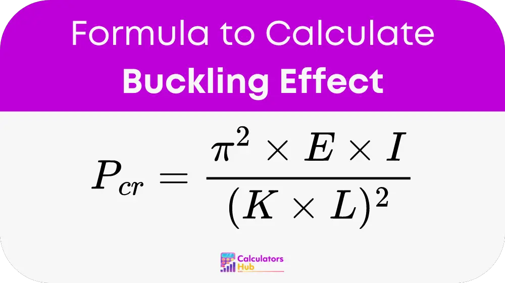
Buckling Effect Formula
To calculate the buckling load, engineers typically use Euler’s Buckling Formula:
Where:
- P_cr: Critical (buckling) load, or the maximum axial load a column can carry before buckling occurs.
- E: Young’s modulus of the material, which indicates the stiffness or elasticity of the material.
- I: Area moment of inertia, which measures the resistance of a cross-section to bending or deflection.
- L: Effective length of the column, which depends on its actual length and boundary conditions.
- K: Effective length factor, which accounts for the end conditions of the column (whether it is fixed, pinned, or free).
Values of K for Different End Conditions:
- K = 0.5: Both ends of the column are fixed, providing maximum resistance to buckling.
- K = 1.0: Both ends of the column are pinned, allowing it to rotate but not translate.
- K = 2.0: One end is fixed, while the other is free, providing minimal resistance to buckling.
Explanation of Terms:
- Critical Load (P_cr): This is the load at which the column will start to buckle under axial compression.
- Young’s Modulus (E): This represents the material’s stiffness. A higher value of E means the material is stiffer and less prone to deformation.
- Moment of Inertia (I): This property depends on the shape and size of the cross-section of the column. It determines the column’s ability to resist bending.
- Effective Length (L): This is the length of the column adjusted based on its support conditions, which influence its buckling behavior.
- Effective Length Factor (K): This factor adjusts the actual length of the column for the effect of end conditions.
This formula is crucial for designing safe and efficient structures, as it helps ensure that columns and beams will not buckle under normal working loads.
Reference Table for Common Column Scenarios
Below is a table that shows typical values for critical loads under different conditions, which can serve as a quick reference for commonly used materials and dimensions:
| Material | Young’s Modulus (E) (GPa) | Column Length (L) (m) | Moment of Inertia (I) (cm^4) | Effective Length Factor (K) | Critical Load (P_cr) (kN) |
|---|---|---|---|---|---|
| Steel | 200 | 3.0 | 800 | 1.0 | 657.98 |
| Aluminum | 69 | 2.5 | 500 | 1.0 | 136.47 |
| Concrete | 25 | 4.0 | 1000 | 0.5 | 96.87 |
| Timber | 12 | 3.5 | 400 | 2.0 | 22.98 |
This table provides quick reference data for various materials and dimensions, making it easier to estimate buckling loads without performing manual calculations.
Example of Buckling Effect Calculator
Let’s walk through an example to illustrate how the buckling load is calculated.
Given:
- The material is steel with a Young’s modulus (E) of 200 GPa.
- The column has a square cross-section with an area moment of inertia (I) of 1000 cm^4.
- The column’s effective length (L) is 4 meters.
- The column has pinned ends, meaning the effective length factor (K) is 1.0.
Using the formula:
P_cr = (π² × E × I) / (K × L)²
P_cr = (π² × 200 GPa × 1000 cm^4) / (1.0 × 4 m)²
First, convert the units to match (make sure to convert I from cm^4 to m^4):
- I = 1000 cm^4 = 1.0 × 10^-6 m^4
- E = 200 GPa = 200 × 10^9 Pa
Now calculate:
P_cr = (π² × 200 × 10^9 × 1.0 × 10^-6) / (1.0 × 4)²
P_cr = 4921.42 / 16 ≈ 307.59 kN
Conclusion: The critical buckling load for this steel column is approximately 307.59 kN. This is the maximum axial load the column can withstand before it buckles.
Most Common FAQs
The buckling of a column depends on several factors, including:
Material properties (such as Young’s modulus).
Cross-sectional shape and area moment of inertia, which influence the column’s resistance to bending.
Column length and its effective length, which is impacted by the column’s end conditions (pinned, fixed, or free).
Applied load, where excessive axial force causes the column to buckle.
The effective length factor (K) adjusts the actual length of the column for its boundary conditions. For example, a column with both ends pinned will have an effective length equal to its actual length (K = 1), while a column with both ends fixed will have an effective length shorter than its actual length (K = 0.5). The smaller the value of K, the more resistant the column is to buckling.
To increase the buckling load of a column, you can:
Use a stiffer material with a higher Young’s modulus (E).
Increase the area moment of inertia (I) by choosing a cross-section with more resistance to bending, such as an I-beam or hollow tube.
Reduce the effective length (L) by improving end support conditions (for example, using fixed rather than pinned supports).