This calculator assists in determining the appropriate wire size needed for the secondary side of a transformer based on the electrical load and distance. Correct wire sizing is crucial to prevent overheating, voltage drop, and potential failures in electrical systems.
Formula
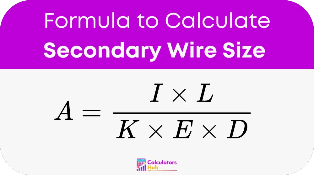
To calculate the secondary wire size for a transformer, the following formula is used:
Where:
- A is the cross-sectional area of the wire in circular mils (CM).
- I is the current in amperes.
- L is the length of the wire in feet.
- K is a constant (12 for copper, 19 for aluminum).
- E is the voltage drop per 1000 feet (typically set to 3 percent of the operating voltage).
- D is the permissible voltage drop in volts.
To find the current (I), use the formula:
I = P / V
Where P is the power in watts and V is the secondary voltage in volts.
Measure the length of the wire run (L) from the transformer to the load. Use the constant K based on the wire material (12 for copper, 19 for aluminum). Calculate the permissible voltage drop (E). For a 3 percent drop in a system with voltage V, E can be calculated as:
E = 0.03 * V
Plug these values into the first formula to find the cross-sectional area (A) in circular mils.
Table for General Terms
| Term | Definition |
|---|---|
| CM | Circular Mils – A unit of measure for the cross-sectional area of a wire. |
| Ampere | The unit of electric current. |
| Voltage Drop | The reduction in voltage in the wire as electricity flows through it. |
Example
Consider a scenario where you need to install a wire for a 480-watt system with a secondary voltage of 120 volts, over a distance of 50 feet using copper wires. Using the formulas provided:
I = 480 / 120 = 4 amperes
E = 0.03 * 120 = 3.6 volts
Plugging these values into the wire size formula:
A = (4 * 50) / (12 * 3.6 * 3.6) = approximately 115 circular mils
Most Common FAQs
A1: “K” is a constant that represents the resistivity of the material; 12 for copper and 19 for aluminum.
A2: “E” is calculated as 3% of your system’s operating voltage, representing the acceptable voltage drop per 1000 feet.
A3: Yes, this calculator is versatile and can be used for a wide range of transformer sizes and applications.