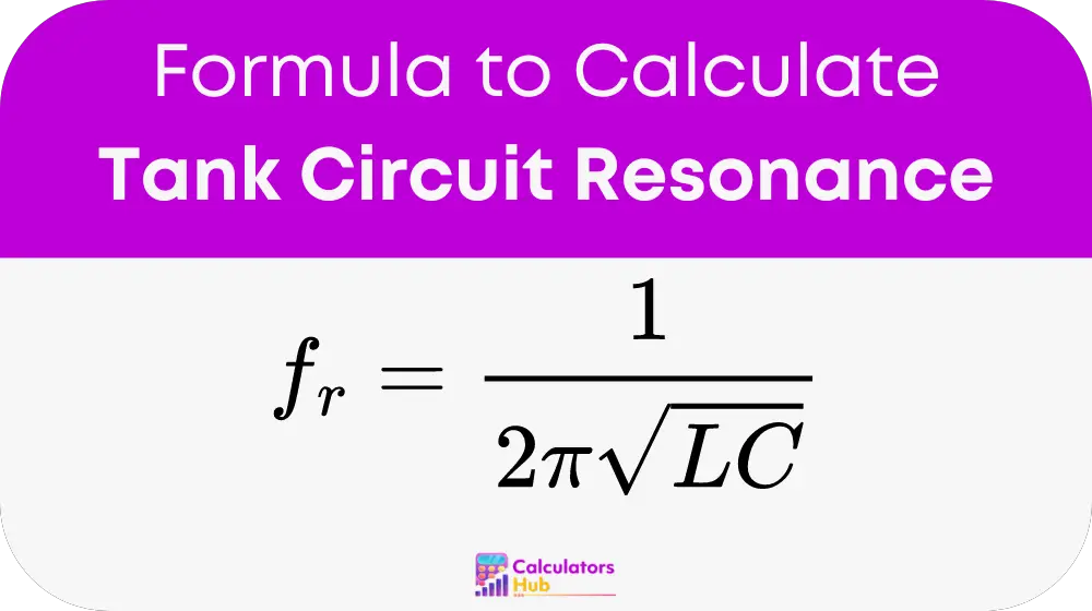
A tank circuit achieves resonance when the reactances of the inductor and the capacitor balance out, maximizing the circuit's impedance and thus its efficiency at a specific frequency known as the resonant frequency (fr). The Tank Circuit Resonance Calculator is designed to compute this frequency based on the inductance (L) and capacitance (C) values provided, offering a quick, reliable means to enhance circuit performance.
The Formula of Tank Circuit Resonance Calculator
The fundamental formula the calculator uses is:

Where:
- fr is the resonant frequency in Hertz (Hz),
- L is the inductance in Henrys (H),
- C is the capacitance in Farads (F).
This formula is derived from the principles of LC circuits where the inductive and capacitive reactances equate, leading to the peak impedance at the resonant frequency.
Useful Reference Table for Quick Calculations
| Inductance (L) | Capacitance (C) | Resonant Frequency (fr) |
|---|---|---|
| 10 mH | 100 pF | 503.29 kHz |
| 1 mH | 1 nF | 159.15 kHz |
| 100 μH | 10 nF | 50.33 kHz |
This table provides typical inductance and capacitance values along with their corresponding resonant frequencies, enabling users to estimate the frequency without performing calculations manually.
Example of Tank Circuit Resonance Calculator
To illustrate, let’s calculate the resonant frequency for an inductor of 1 mH and a capacitor of 1 nF:
fr = 1 / (2 * pi * sqrt(1 * 10^-3 * 1 * 10^-9)) ≈ 159.15 kHz
This example shows how changing L and C values impacts fr, providing insights into tuning the circuit's performance.
Most Common FAQs
A tank circuit consists of an inductor and a capacitor connected either in series or parallel, used primarily to filter signals at its resonant frequency.
The resonant frequency determines where the circuit can efficiently filter or amplify signals. Crucial in applications like radio transmitters and audio electronics.
Inductance and capacitance can be measured using an LC meter. Which provides quick and accurate readings essential for designing effective tank circuits.